

This is Week 11. Input devices, we are going to use the electronic circuit from week 08. During several weeks we have been working with the board we design. Now we have to add some new things to it, i'm talking about input devices, this devices are use to make a component, like a screen, work. So, lets start and see what comes along this week, of course hoping for the best and trying to enjoy as much as I can! Let me share with all of you what are my new assignments:
This week assignmets are:
Group assignments:
Individual assignments:
| Machines/Equipment | Components |
|---|---|
|
|
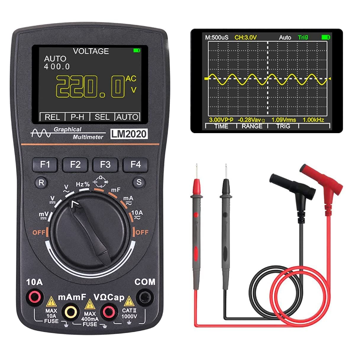
Multimeter
A digital multimeter (DMM) is a versatile electronic device used to measure various electrical properties, including voltage, current, and resistance. The device displays the measurements on a digital screen, making it easy to read and understand the results accurately. Digital multimeters have replaced traditional analog meters and offer higher accuracy, reliability, and better handling of impedance.
A multimeter is used to troubleshoot electrical problems on motors, circuits, power supplies, and switches. It is the most common tool used by technicians to troubleshoot electrical issues. A few examples of use cases are:
Data from: Multimeter
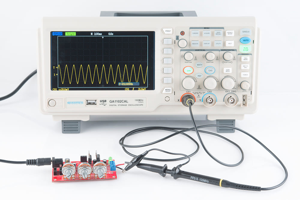
Oscilloscope
Is a tool that displays electric voltage signals over time as a waveform graph. The vertical axis (Y) represents the voltage measurement, and the horizontal axis (X) represents time. Sometimes, a Z-axis is displayed as color grades or brightness that represents the intensity of the voltage. The voltage signals are displayed as wavelengths oscillating or repeating variations over time. While oscilloscopes are most commonly used by engineers or electrical technicians, most people will see oscilloscopes in the medical field, whether in person or through movies or television. Typically, the oscilloscope displays a medical patient's heartbeat or brain waves.
Data from: Oscilloscope
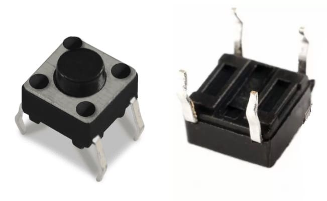
Is a mechanical device used to control an electrical circuit in which the operator manually presses a button to actuate an internal switching mechanism. They come in a variety of shapes, sizes, and configurations, depending on the design requirements.
Data from: Push button
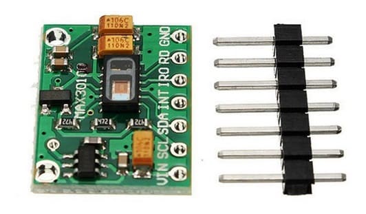
Is an integrated pulse oximetry and heart-rate monitor module. It includes internal LEDs, photodetectors, optical elements, and low-noise electronics with ambient light rejection. It provides a complete system solution to ease the design-in process for mobile and wearable devices.
Data from: Max30102

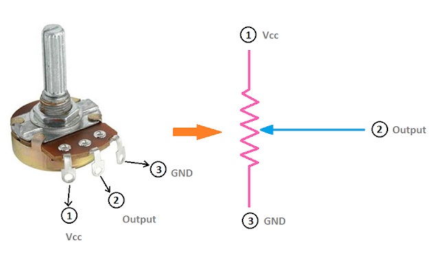
Is a manually adjustable variable resistor with 3 terminals. Two of the terminals are connected to the opposite ends of a resistive element, and the third terminal connects to a sliding contact, called a wiper, moving over the resistive element. It functions as a variable resistance divider.
Data from: Potentiometer
Before testing some input devices I got to make sure to know about them, I mean understand the hardware and technical information of each on of them and learn how to connect them. After that test the analog and digital level of both device. The input devices i'm using are:
The first terminal, or terminal 1, is your ground. The middle terminal, or terminal 2, is the input signal for the pot. The third terminal, or terminal 3, is your output signal. The shaft on top controls a small ring attached to the second terminal. Turning it controls how low or high the input is.
Pots are rarely used to control signals that are more than a couple of volts, but the amount of resistance that they provide is important. The higher the range, the more control you’ll have over your device. The number on the front of the pot tells the highest level of resistance that the pot can achieve. So a 200K pot can provide a maximum of 200,000 ohms of resistance.
Place your pot down on a flat surface next to your electronic device. If you know that you’re going to install the pot in a particular location, start there. Turn the 3 terminals so that they’re facing you. Remove any panels on your electronic device to expose the backside of any input or output ports. Unplug your electronic device before opening any panels or soldering any connections. You don’t want to get electrocuted or damage your device permanently.
Place your pot down on a flat surface next to your electronic device. If you know that you’re going to install the pot in a particular location, start there. Turn the 3 terminals so that they’re facing you. Remove any panels on your electronic device to expose the backside of any input or output ports. Unplug your electronic device before opening any panels or soldering any connections. You don’t want to get electrocuted or damage your device permanently.
Connect the voltmeter's terminals to the input and output terminals on the pot. Turn the voltmeter on and turn the dial to feed a signal. Turn the knob on top of your pot to adjust the signal. If the signal reading on the voltmeter goes up and down when you turn the knob, your potentiometer works. Turn your electronic device on and feed a signal to the pot by playing some music, hitting a guitar note, or turning a light on. Twist the shaft to the left to turn the audio or light down. Twist the shaft to the right to raise the volume or level of light. Twist the shaft all the way to the left to turn the output off.
Data from: Wiring a potentiometer
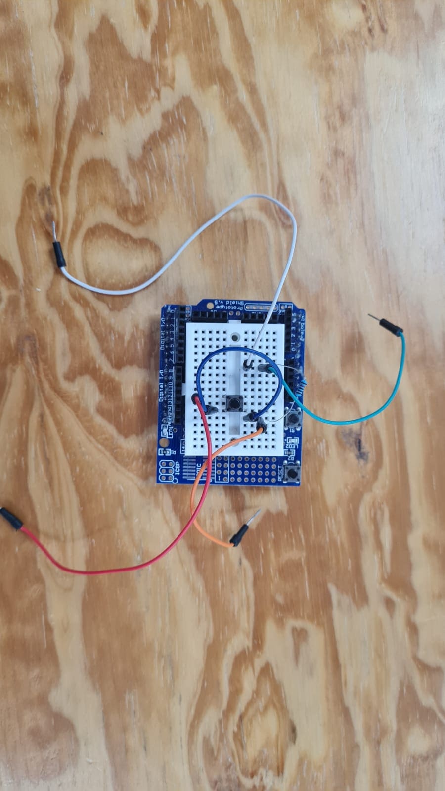
Connect three wires to the board. The first two, red and black, connect to the two long vertical rows on the side of the breadboard to provide access to the 5 volt supply and ground. The third wire goes from digital pin 2 to one leg of the pushbutton. That same leg of the button connects through a pull-down resistor (here 10K ohm) to ground. The other leg of the button connects to the 5 volt supply. When the pushbutton is open (unpressed) there is no connection between the two legs of the pushbutton, so the pin is connected to ground (through the pull-down resistor) and we read a LOW. When the button is closed (pressed), it makes a connection between its two legs, connecting the pin to 5 volts, so that we read a HIGH.
You can also wire this circuit the opposite way, with a pullup resistor keeping the input HIGH, and going LOW when the button is pressed. If so, the behavior of the sketch will be reversed, with the LED normally on and turning off when you press the button. If you disconnect the digital I/O pin from everything, the LED may blink erratically. This is because the input is "floating" - that is, it will randomly return either HIGH or LOW. That's why you need a pull-up or pull-down resistor in the circuit.
Data from: Push button
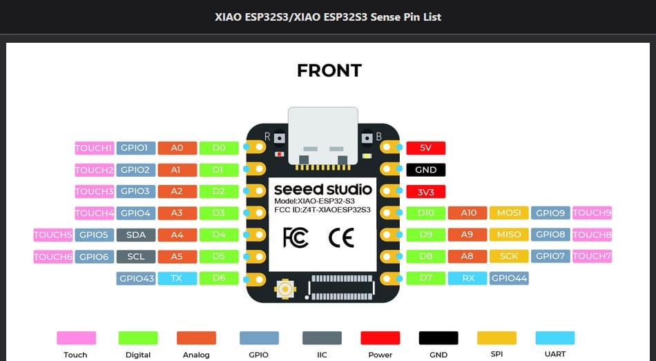
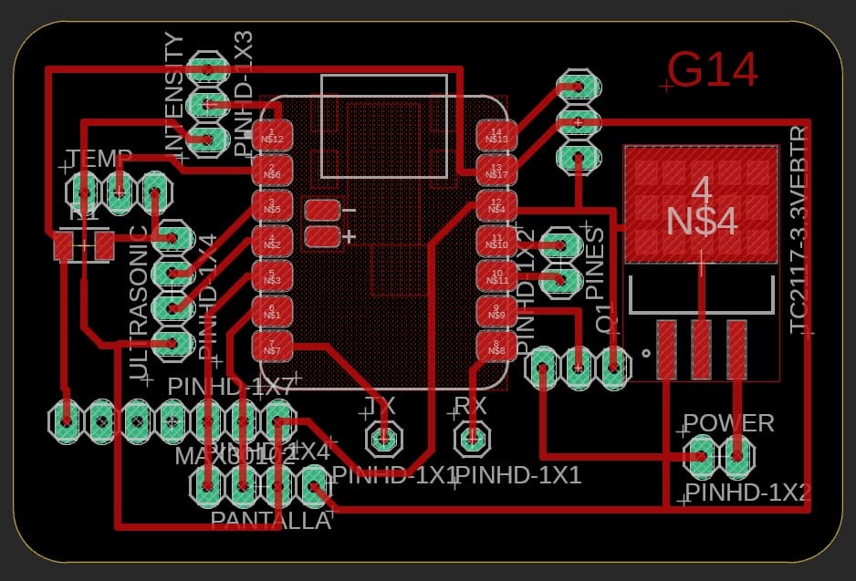
This is the pin diagram of the XIAO_ESP32S3 and the circuit board just to have a better understanding on were to connect the input devices

This is some information about the max30102 sensor.
The MAX30102 operates on a single 1.8V power supply and a separate 3.3V power supply for the internal LEDs. Communication is through a standard I2C-compatible interface.
Data from: Max30102
The MAX30102 works by shining both lights onto the finger or earlobe (or essentially anywhere where the skin isn’t too thick, so both lights can easily penetrate the tissue) and measuring the amount of reflected light using a photodetector. This method of pulse detection through light is called Photoplethysmogram. The working of MAX30102 can be divided into two parts: Heart Rate Measurement and Pulse Oximetry (measuring the oxygen level of the blood).
The oxygenated hemoglobin (HbO2) in the arterial blood has the characteristic of absorbing IR light. The redder the blood (the higher the hemoglobin), the more IR light is absorbed. As the blood is pumped through the finger with each heartbeat, the amount of reflected light changes, creating a changing waveform at the output of the photodetector. As you continue to shine light and take photodetector readings, you quickly start to get a heart-beat (HR) pulse reading.
Pulse oximetry is based on the principle that the amount of RED and IR light absorbed varies depending on the amount of oxygen in your blood.
Data from: How does it work
After verifying some information about the Max3102 sensor and as my next part of the assignment, I wire it to the circuit board I design a few weeks ago. For this part i'm going to need 4 wires and connect them to the next pins:
After wiring the max30102 sensor, we have to use some libraries and upload them to the Arduino IDE. In the file section you can download the libraries I use to test the sensor. Remember its important to take time and verify the code works properly. Now in the next videos you can see the results I got of the measurements of the sensor.
In this first result you can see the heart rate and SPO2 at the same time every 4 seconds.

In the second test the measures are the heart beat and SPO2 continuously. It also shows when the sensor is not detecting the finger.
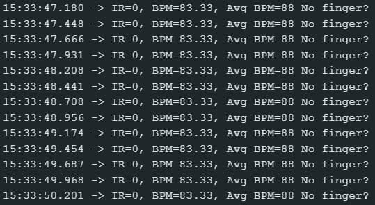
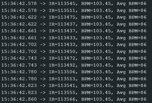
In the third test the measures the heart beat as a number and as a graph. I this one I use the serial plotter provided by the Arduino IDE (go to tools and select Serial plotter).
For my final result I decided to test the heart beat and SPO2 and compare it with a oximeter. I did this to verify how accurate the Max30102 is.
In this part you can download the arduino libraries I use during this week assignments.
What did I learn in this week?